3.1 Acid Corrosion
- Category: Process defect
- Sub category: Anodising defect
- Defect type: Pitting
- Defect visible after: Etching / Anodising / Colouring / Sealing
- Defect description:
Random, often isolated, large and deep pits. It should be possible to detect corrosion product in the pits, if the pitting is observed before etching and anodising. If the pits, which are usually intergranular in nature, have been etched and anodised they will be clean and have an anodic film down inside the pit.
- Defect cause:
Accidental splashing of aluminium parts with acids, usually when stored in the anodising plant can cause pitting before anodising. Chlorinated solvents are now much less widely used for degreasing. By hydrolysis hydrochloric acid can be form in such solvents. droplets of trichlorethylene vapour condensate, because they contain HCl, they have been known to cause acid pitting.
- Defect remedy:
The best way to avoid to avoid this type of corrosion is a better housekeeping and storage of the sections. Once pitting has occured, it is usually so deep that it is impossible to revamp the section.
3.2 Alkali Corrosion
- Category: Process defect
- Sub category: Anodising defect
- Defect type: Pitting
- Defect visible after: Etching / Anodising
- Defect description:
The pit is well-rounded with no intergranular corrosion.
- Defect cause:
In the most cases alkali ptting is caused by mortar, cement dust or wet alkaline splashes. Other causes are caustic etch spray or accidental spillage of caustic chemicals.
- Defect remedy:
The best way to avoid to avoid this type of corrosion is a better housekeeping and storage of the sections. Once pitting has occured, it is usually so deep that it is impossible to revamp the section.
3.3 Anodising Burn
- Category: Process defect
- Sub category: Anodising defect
- Defect type: Non-uniformity
- Defect visible after: Anodising
- Defect description:
Bright areas on anodic coating surrounded by black or darker area, usually no anodic film or very soft film present in the defective area.
- Defect cause:
Anodising burn is caused by excessive current densities and insufficient agiation or movement of the anodising electrolyte across the workpiece. Also it can be caused by a poor electrical contact between the rack/jig and the aluminium being anodised.
- Defect remedy:
Check concentration of the anodising electrolyte and that its temperature is under control. Improve agitation of the anodising electrolyte and/or reduce the anodising current density. Increase/Improve electrical contact area between rack/jig and aluminium being anodised that it is adequate to carry current.
3.4 Chloride Corrosion
- Category: Process defect
- Sub category: Anodising defect
- Defect type: Pitting
- Defect visible after: Anodising
- Category: Process defect
- Sub category: Anodising defect
- Defect type: Pitting
- Defect visible after: Anodising
- Defect description:
Such pitting has a very distinctive form, the pits are star shaped and on all faces of the sample . They are relatively deep and, as such, are usually black in appearance (scattered light trapping) There is no anodic film over the pits.
- Defect cause:
Exceeding a critical level of chloride of 80ppm measured as the Cl - ion in a sulphuric acid electrolyte, can cause a corrosion of the highly active aluminium during the anodising process. Oxalic acid electrolytes are even more sensitive to Cl (about 10ppm as Cl ion).
- Defect remedy:
The use of deionised water for anodising electrolyte make-up and top-up as well as for other critical processes / rinses is the most satisfactory method of eliminating this problem.
3.5 Colour Differences
- Category: Process defect
- Sub category: Anodising defect
- Defect type: Non-Uniformity
- Defect visible after: Colouring
- Defect description:
Colour differences are visually detectable. The colour range between extrusions is outside the agreed upper and lower colour limits and is known as a poor colour match.
- Defect cause:
There are many different causes: 1. Inconsistency or differences of the alloy 2. Some extrusions taking up more dye or pigment than other. 3. Differences in the anodising parameter. 4.Incorrect dyeing conditions. 5. Lack of control of electrolytic colouring process.
- Defect remedy:
3. Check anodising solution concentration, pH, anodising time and temperature. 4. Check dye solution concentration, pH and for contamination with sulphates and chlorides. Check dyeing time and temperature. Check pH of post anodising rinse is below 2,0. 5. In the case of electrolytic colouring this can be due to the use of the wrong colouring conditions or contamination of the colouring electrolyte with sodium. The racking geometry can also affect colour uniformity within a load as can the choice of the voltage time programs used. Check process suppliers recommended practices and electrolyte concentrations and ensure the operation is controlled within these limits. Also check if variation is within a load or from load to load. If latter check consistency of anodising and colouring practices. Recovery: Strip and reprocess affected extrusions.
3.6 Comet Tails
- Category: Process defect
- Sub category: Pretreatment chemical polishing defect
- Defect type: Non-uniformity
- Defect visible after: Brightening / Anodising
- Defect description:
Vertical (transverse to extrusion direction) comet tails / gas marks.
- Defect cause:
Gas marks caused by evolution of hydrogen gas during chemical polishin, often initiated by dried on polishing compound.
- Defect remedy:
Move jig / flight bar during chemical polishing. Improve degreasing to remove all polishing compound.
3.7 Crazing
- Category: Process defect
- Sub category: Anodising defect
- Defect type: Non-uniformity
- Defect visible after: Sealing
- Defect description:
Hairline cracks in the anodic coating.
- Defect cause:
This defect can be caused by stress produced in the anodic oxide coating when profiles are transferred from rinse tank to sealing tank. Because of the differences in thermal expansion coefficient between the anodic oxide coating and the aluminium hairline cracks can develop. Also the hairline cracks can occur because of a mechanical deformation of an anodised extrusion by bending or impact. The defect is enhanced by high current densities, low electrolyte temperatures and thick oxide films (hard anodising conditions). Stress introduced to the Al profile surface due to machining generates more susceptible material for crazing. Anodic oxide coatings exposed to high ambient temperatures (e.g. lighting) and strong sunlight are more likely to develop crazing than those exposed in the more temperate climates.
- Defect remedy:
Carry out stabilising heating of the machined profiles to even out stress in the material (e.g. 130 °C for 40 minutes). Reduce current density (1.4-1.6 A/dm2). Electrolyte temperature should be around 20 °C. Keep anodic film thickness below 30 µm and reduce thermal shock by immersing anodised parts in water at 70°C before immersing in boiling water seal. Do not heat thick anodic films above 120°C. Any bending of the extrusion should be carried out before anodising. For reprocess Strip anodic film and anodise again.
3.8 Etch Staining
- Category: Process defect
- Sub category: Anodising defect
- Defect type: Non-uniformity
- Defect visible after: Etching / Colouring
- Defect description:
Staining on an extruded section after etching. In some cases this may not be immediately visible after etching and may not be seen until later in the process.
- Defect cause:
Due to etch solution drying on the extruded section surface during transfer to the post etch rinse and staining due to preferential etch in this area. Poor cleaning / rinsing after etching. Long time between etching and rinsing. Slow movement / speed of crane. Wrong composition of etch solution. Too high temperature of the profile surface as a consequence of wrong etch composition, no cooling of the etch tank and thick walled profiles. Poor jigging in combination with poor cleaning.
- Defect remedy:
Check that the level of wetting agent in the etching solution is adequate. Improve transfer time from etching stage to post etch rinse stage. Ensure that the etch solution temperature is not too high; ideally it should not exceed 60°C. Ensure good and fast rinsing / cleaning of the profile surfaces after etching. Proper jigging of difficult and / or thick walled profiles.
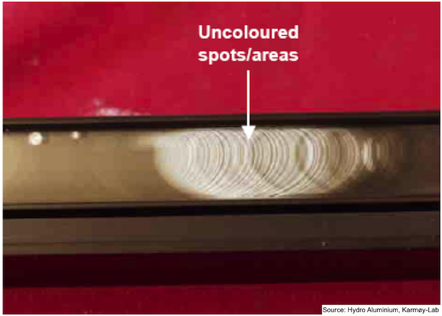
3.9 Gas Trapping
- Category: Process defect
- Sub category: Anodising defect
- Defect type: Non-uniformity
- Defect visible after: Anodising / Colouring
- Defect description:
Random spots or areas which are uncoloured, different hue or lighter on the underside of the racked workpiece. Often the anodic film is thinner. Electro-coloured or dyed finishes the colour can be lighter or darker depending on the used method of colouring.
- Defect cause:
From the air agitation system or gas evolved by electrochemical reactions in the anodising or colouring process air or gas bubbles can be trappeed on the underside of the racked workpiece. These air or gas pockets operate as insulators for the anodising process or masking agents for the colouring process.
- Defect remedy:
Rack the workpiece that there are no horizontal flat surfaces or inverted channels on the underside so that the gas can escape. Recovery is possible if the affected workpieces are stripped and reprocessed. Racked in a way that the air or gas trapping is eliminated.
3.10 Hot Spots
- Category: Process defect
- Sub category: Extrusion defect
- Defect type: Non-uniformity
- Defect visible after: Anodising
- Defect description:
Characteristically appear as dark (grey or black) rough patches, at regular or random intervals along the extruded length. If the defective sample is etched in a 10% NaOH etching solution at 60°C a heavy black smut will be observed in the area of the hot spot.
- Defect cause:
This is a metallurgical problem, not an anodising fault. The defect is caused by a coarser Mg2Si precipitation in these areas, due to differential cooling on the extrusion run-out table or walking beam. The hardness of the aluminium in the black spot area is usually significantly lower than the typical hardness of the rest of the extrusion.
- Defect remedy:
Controlling the time the hot sections are allowed to stand on the run-out table or the walking beam slats, when the extrusion is at a temperature higher than 230°C, should help to eliminate the problem. Forced air-cooling and purpose-designed materials, such as Kevlar or Railco, formulated to reduce the rate of heat conductivity from the extrusion have practically eliminated this problem. A cooling rate on the extrusion run-out table of 1°C per second, down to 200°C, is considered to be typical for a good air quench on 6063 alloy extrusions.
3.11 Insufficient Degreasing
- Category: Process defect
- Sub category: Anodising defect
- Defect type: Non-uniformity
- Defect visible after: Etching / Brightening
- Defect description:
Non uniform Degreasing.
- Defect cause:
Because of a poor degrease solution or practice (e. g. temperature too low) oil or grease is still left on some areas of the sections of the aluminium being anodised. This leads to differential etching/brightening of the section surface.
- Defect remedy:
Renew the degreasing solution or extend the treatment time or increase the temperature. It is difficult to recover such workpieces which are insufficient degreased.
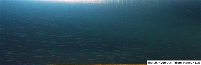
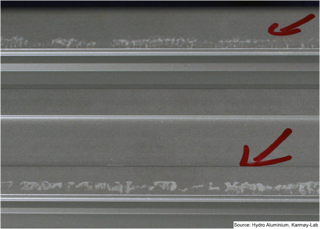
3.12 Pick Ups
- Category: Process defect
- Sub category: Extrusion defect
- Defect type: Streaks of flecks
- Defect visible after: Anodising
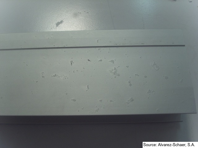
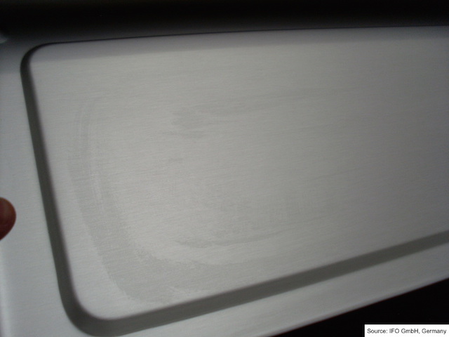
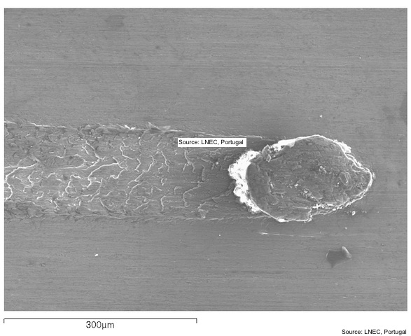
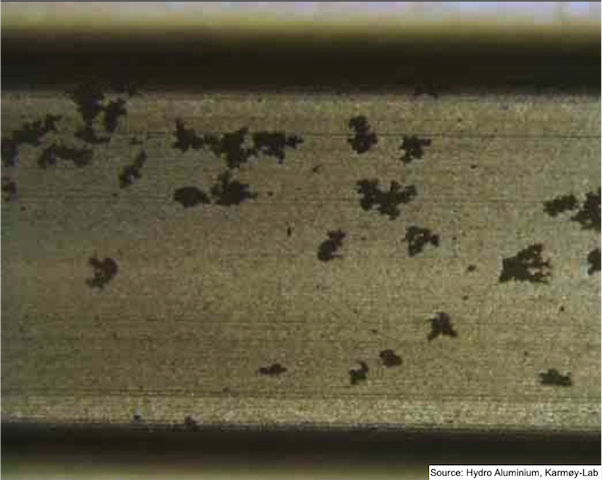
- Defect description:
Usually scuff marks of various intensity, in more severe cases there is often a deposit at th end of the scuff mark. Present to some degree on most extrusions.
- Defect cause:
Various parameters such as extrusion temperature, extrusion speed and condition of die bearing surface can all influence the occurrence and severity of pick ups.
- Defect remedy:
Good control of extrusion parameters that can affect surface quality.
3.12 Pick Ups - Defect Picture 1
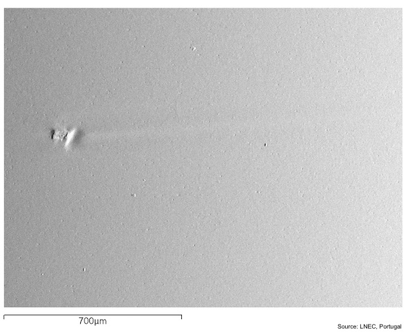
3.12 Pick Ups - - Defect Picture 2
- Category: Process defect
- Sub category: Extrusion defect
- Defect type: Streaks of flecks
- Defect visible after: Anodising
- Defect description:
Usually scuff marks of various intensity, in more severe cases there is often a deposit at th end of the scuff mark. Present to some degree on most extrusions.
- Defect cause:
Various parameters such as extrusion temperature, extrusion speed and condition of die bearing surface can all influence the occurrence and severity of pick ups.
- Defect remedy:
Good control of extrusion parameters that can affect surface quality.
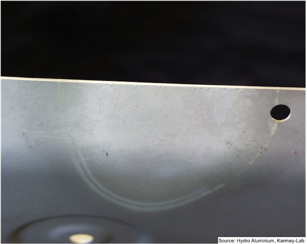
3.13 Pitting Corrosion
- Category: Process defect
- Sub category: Anodising defect
- Defect type: Pitting
- Defect visible after: Develop in service
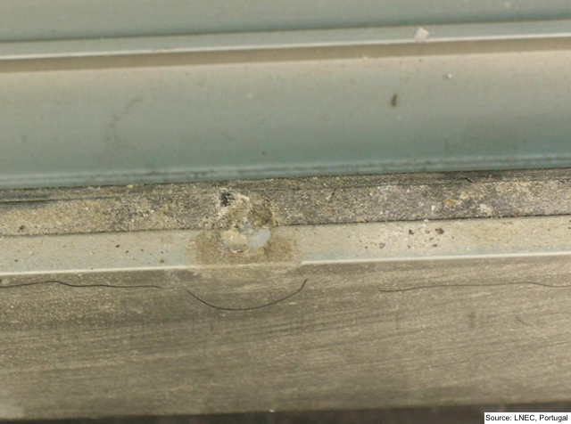
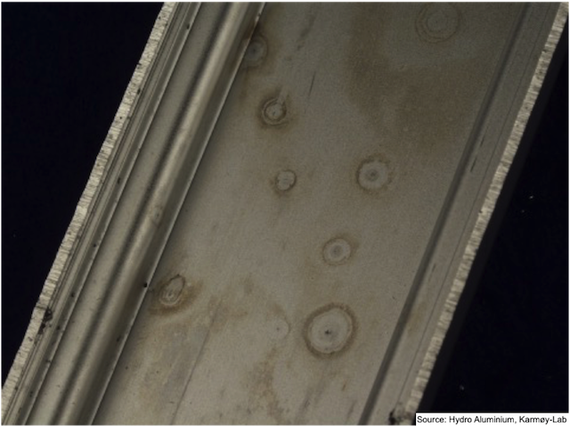
- Defect description:
Corrosion in the form of liitle holes - pitting corrosion that penetrates the anodic film. Each pit often surrounded by a halo of corrosion product.
- Defect cause:
Anodic films not formed according to the relevant specifications, may show premature deterioration in service with anodic films of inadequate film thickness and in some cases, with very low hardness values. Contamination of one or more of the rinse tanks after the anodising step. Contamination of one or more of the process tanks after the anodising step: Colouring tank (when colour anodising) and sealing tank. Chloride is the most likely reason for contamination. Mains / tap water may contain a lot of chloride.
- Defect remedy:
In service pitting usually occurs due to inadequate anodic film thickness for particular environment. Poor quality of the (soft) anodic film. Lack of regular cleaniing or maintenance of the anodic finish in service. Over pigimentation in black electrolytic coloured finishes. Check the quality of the make up water (mains / tap water) in the different tanks. The max amount of chloride should be 50 ppm to avoid chloride pitting. Rinsing tanks should not be used as buffer tanks for the flight bars waiting to be anodised. Desmut tank is the correct tank to use as buffer tank.)
- Category: Process defect
- Sub category: Anodising defect
- Defect type: Pitting
- Defect visible after: Develop in service
- Defect description:
Corrosion in the form of liitle holes - pitting corrosion that penetrates the anodic film. Each pit often surrounded by a halo of corrosion product.
- Defect cause:
Anodic films not formed according to the relevant specifications, may show premature deterioration in service with anodic films of inadequate film thickness and in some cases, with very low hardness values. Contamination of one or more of the rinse tanks after the anodising step. Contamination of one or more of the process tanks after the anodising step: Colouring tank (when colour anodising) and sealing tank. Chloride is the most likely reason for contamination. Mains / tap water may contain a lot of chloride.
- Defect remedy:
In service pitting usually occurs due to inadequate anodic film thickness for particular environment. Poor quality of the (soft) anodic film. Lack of regular cleaniing or maintenance of the anodic finish in service. Over pigimentation in black electrolytic coloured finishes. Check the quality of the make up water (mains / tap water) in the different tanks. The max amount of chloride should be 50 ppm to avoid chloride pitting. Rinsing tanks should not be used as buffer tanks for the flight bars waiting to be anodised. Desmut tank is the correct tank to use as buffer tank.)
3.14 Polishing Drag Marks
- Category: Process defect
- Sub category: Polishing defect
- Defect type: Non-uniformity
- Defect visible after: Polishing / Anodising
- Defect description:
Horizontal (along the extrusion direction) marks.
- Defect cause:
Impurities / pores in the profile surface. Impurities in the polishing paste. Impurities on the brush / mop used for mechanical polishing.
- Defect remedy:
Ensure profile surface free of impurities prior to polishing. Ensure no impurities on the mop / brush or in the paste prior to polishing.
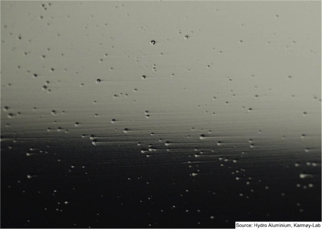
3.15 Rinse Water Corrosion
- Category: Process defect
- Sub category: Anodising defect
- Defect type: Pitting
- Defect visible after: Anodising
- Defect description:
Rinse water corrosion is always very shallow and the pits usually look very white and are often star shaped. Rinse water corrosion always occurs before the anodizing stage and therefore will be covered by an anodic film.
- Defect cause:
Corrosion of the active Aluminium surface due to aggressive rinse water and / or too long rinse times. Rinse water corrosion can occur in very clean rinses if the water supply contains chlorides. Some alloys are more prone to rinse water corrosion than others e.g. 5005 type.
- Defect remedy:
Once it is established in which rinse tank it is occurring, rinse water corrosion can be usually prevented by the addition of a small amount (0.5%) of an oxidising acid, such as nitric acid, to the offending rinse tank. In addition the rinse time could be reduced and the rinse water quality could be improved. NOTE: A rinse contaminated with process solution is often less likely to produce rinse water corrosion than a very clean mains water rinse containing normal chloride levels added by the water supply company.
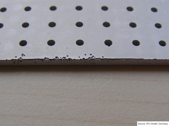
3.16 Spalling
- Category: Process defect
- Sub category: Anodising defect
- Defect type: Pitting
- Defect visible after: Anodising / Colouring
- Defect description:
Spalling or film detachment on natural anodised coatings is rare. It is more common on electrolytic coloured coatings particularly those produced in cobalt or nickel based electrolytes. Spalling of parts of the anodising layer, best visible on coloured anodising layers.
- Defect cause:
In the case of natural anodised coatings spalling usually occurs when duplex films are produced by stopping the anodising process and restarting it. With electrolytic colouring it can be caused by a too high colouring voltage (current density) or contamintion of the colouring electrolyte with Na ions . One cause can be corrosion underneath the layer in the case where the base material contains higher quantities of zinc.
- Defect remedy:
With natural anodising do not stop and start the process part way through an anodising cycle. With electrolytic colouring reduce colouring voltage (current density) and in the case of Ni or Co based electrolytes keep Na content below critical level for spalling. This can be done by good house keeping (minimise contamination from caustic soda solutions) or the use of ion exchange on the colouring electrolyte to remove the sodium. Careful process optimization preventing the corrosion of zinc on the layer surface.
3.17 Brightness Differences
- Category: Process defect
- Sub category: Anodising defect
- Defect type: Non-uniformity
- Defect visible after: Anodising
- Defect description:
Variation in brightness of extrusions produced on same load or even on one extruded length.
- Defect cause:
Metallurgical variation affecting etching, brighteninig or anodising response.
- Defect remedy:
Check ingot source, do not mix ingots from diffeent suppliers or remelt with smelter ingot. Check ageing practices to ensure there is not a large differrence in the distribution and size of Mg2Si precipitate.
3.18 Chalking
- Category: Process defect
- Sub category: Anodising defect
- Defect type: Non-uniformity
- Defect visible after: Develop in service
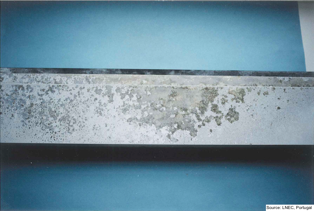
- Defect description:
A white bloom formation occurring in service that can be removed by aggressive abrasion.
- Defect cause:
Due to a slightly soft anodic coating resulting from anodising at too high an electrolyte temperature or too low a current density. Usually confined to anodic film thicknesses of 20 µm or higher.
- Defect remedy:
Use anodising conditions that produce an anodic film of good abrasion resistance and keep anodising electrolyte temperature below 20 °C when producing anodic film thicknesses of 20 µm or greater.
- Category: Process defect
- Sub category: Anodising defect
- Defect type: Non-uniformity
- Defect visible after: Develop in service
- Defect description:
A white bloom formation occurring in service that can be removed by aggressive abrasion.
- Defect cause:
Due to a slightly soft anodic coating resulting from anodising at too high an electrolyte temperature or too low a current density. Usually confined to anodic film thicknesses of 20 µm or higher.
- Defect remedy:
Use anodising conditions that produce an anodic film of good abrasion resistance and keep anodising electrolyte temperature below 20 °C when producing anodic film thicknesses of 20 µm or greater.
3.19 Chatter Marks
- Category: Process defect
- Sub category: Extrusion defect
- Defect type: Non-uniformity
- Defect visible after: Extrusion
- Defect description:
Non uniform surface.
- Defect cause:
Extrusion speed temperature.
- Defect remedy:
This is an extrusion defect that would normally be inspected out before anodising and as such would not be considered to be an 'anodising' defect. Strip and reprocess affected extrusions.
3.20 Die Lines
- Category: Process defect
- Sub category: Anodising defect
- Defect type: Streaking
- Defect visible after: Anodising
- Defect description:
Usually isolated grooves in the as- extruded surface. Depending on the depth, die lines might still appear after etching and could even be visible after mechanical polishing.
- Defect cause:
Caused by damage to the die bearing or the entrapment of dirt, inclusions, steel, e.g. particles of nitrided bearing, pieces of the liner wall or other hard particles in the aluminum coating on the die bearing. Are often visible after extrusion.
- Defect remedy:
Die lines can only be avoided with care in ensuring that the billet and tooling are free of contaminants before and during extrusion. Die lines can be removed by de-anodising and mechanical grinding / polishing and re-anodising.
3.21 Etch Solution Pitting
- Category: Process defect
- Sub category: Anodising defect
- Defect type: Pitting
- Defect visible after: Etching / Anodising
- Defect description:
The defect appears as severe pitting and gas streaking parallel to the vertical axis as loaded in the etch bath. Especially with Al99 if etching in caustic/nitrate solutions.
- Defect cause:
Wrong ratio between caustic soda and sodium nitrate. Etch solution pitting is most common when the caustic content of the etch solution falls below two percent.
- Defect remedy:
Improve the ratio of the etch solution.
3.22 Linishing Operation Streaks
- Category: Process defect
- Sub category: Mechanical pretreatment defect
- Defect type: Non-uniformity
- Defect visible after: Mechanical pretreatment / Etching / Anodising
- Defect description:
Appear as dark streaks generally in extrusion direction associated with small-scale roughening of the extruded surface.
- Defect cause:
The streaks are caused by local surface damage because of worn or defective linishing pads, or poor linishing practice such as application of excessive pressure, causing localized overheating. Aluminium oxide build up on the linishing belt can also be redeposited on the extrusion surface during linishing.
- Defect remedy:
Can be avoided with quality linish pads and practice.
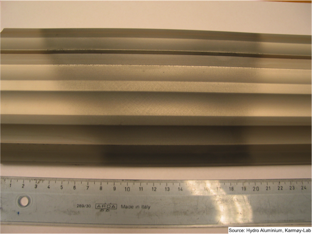
3.23 Longitudinal Weld
- Category: Process defect
- Sub category: Extrusion defect
- Defect type: Streaking
- Defect visible after: Etching / Anodising
- Defect description:
Visible longitudinal lines or streaks, often, in the case of coloured anodising, having uncoloured areas or gassing associated with the linear defect.
- Defect cause:
The longitudinal weld is a junction between metal flowing through adjacent ports in the die and is often highlighted by etching and anodising. These welds can be exaggerated by the inclusion of oxides and intermetallics often associated with back end effects. These inclusions can cause pitting or gassing in the vicinity of the weld. Transverse welds are different in that they exhibit a V-shape interface that moves out towards the location of the longitudinal weld. The more severe transverse welds can add to the severity of the longitudinal weld. Metal flow effects can also enhance longitudinal welds the net result being that the metal in the weld zone may have been more heavily worked. This greater deformation can affect the etching and anodising response in this area.
- Defect remedy:
Attention to the cleanliness and correct preheating of the die tooling, along with ingot preheat temperature and extrusion speed, all contribute towards producing a good quality weld. Die design, particularly the size of the welding chamber, is crucial to producing a good longitudinal weld. The usual remedy is to redesign the die to prevent dead metal zones under optimum extrusion conditions. Affected material generally cannot be recovered by reprocessing and is therefore scrapped. Dies should be designed such that the weld is located on insignificant surfaces of the section or as near to any corners as is practical.
3.24 Transverse Weld
- Category: Process defect
- Sub category: Extrusion defect
- Defect type: Streaking
- Defect visible after: Etching / Anodising
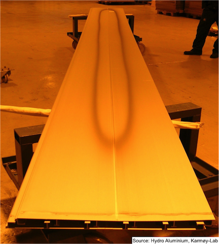
- Defect description:
In extrusion direction longitudinal streaks will appear, usually more prevalent on hollows depending on how near to the front of the extrusion the sample is taken, the streaks may be tapered to a V-shape to the front end.
- Defect cause:
This defect occurs at the front of all extrusions (except the first) with any solid profile produced with a pocket or welding chamber and all hollow shapes. The defect is caused by the unavoidable oxide layer that occurs at the junction between the sheared surface of the aluminum in the ports of the die and the front of the next ingot. It takes the form of a dark V-shaped streak, with the tip of the V pointing towards the front end of the extruded length.
- Defect remedy:
For anodising quality material, it is often (but not always) necessary to cut this material out and scrap a prescribed length at the front of the extruded length. It is also good practice to avoid using ingots of different source, thermal treatment, or cast structure for a given batch. It is difficult to eliminate transverse weld. One option is to reduce the transverse weld length by decreasing the volume of metal in the ports of the die, but this will accentuate the transverse weld (making it shorter if it is to be scrapped). Practices that keep the sheared surface clean help to disguise the transverse welds, such as minimizing the use of lubrication on the shear blade and generally keeping the butt shearing process under good control.
- Category: Process defect
- Sub category: Extrusion defect
- Defect type: Streaking
- Defect visible after: Etching / Anodising
- Defect description:
In extrusion direction longitudinal streaks will appear, usually more prevalent on hollows depending on how near to the front of the extrusion the sample is taken, the streaks may be tapered to a V-shape to the front end.
- Defect cause:
This defect occurs at the front of all extrusions (except the first) with any solid profile produced with a pocket or welding chamber and all hollow shapes. The defect is caused by the unavoidable oxide layer that occurs at the junction between the sheared surface of the aluminum in the ports of the die and the front of the next ingot. It takes the form of a dark V-shaped streak, with the tip of the V pointing towards the front end of the extruded length.
- Defect remedy:
For anodising quality material, it is often (but not always) necessary to cut this material out and scrap a prescribed length at the front of the extruded length. It is also good practice to avoid using ingots of different source, thermal treatment, or cast structure for a given batch. It is difficult to eliminate transverse weld. One option is to reduce the transverse weld length by decreasing the volume of metal in the ports of the die, but this will accentuate the transverse weld (making it shorter if it is to be scrapped). Practices that keep the sheared surface clean help to disguise the transverse welds, such as minimizing the use of lubrication on the shear blade and generally keeping the butt shearing process under good control.
3.25 Patchy Coloured Finishes
- Category: Process defect
- Sub category: Anodising defect
- Defect type: Non-uniformity
- Defect visible after: Colouring
- Defect description:
A non-uniform cloudy patchy uptake of pigment in the anodic film during colouring in a dye solution or by electrolytic pigmentation.
- Defect cause:
Due to precipitation of gelatinous aluminium hydroxide in the pores of the anodic film inhibiting or slowing down dye or pigment uptake.
- Defect remedy:
Usually due to the post anodising rinse being too clean. Make sure this rinse is always at pH 2.0 or lower by adding sulphuric acid if necessary. Time in this rinse should be at least 1 minute with good movement of the rinse water over the parts by agitation or up and down movement of the load. Do not leave the load in a low pH for more than 5 minutes as it may soften the anodic film. Recovery - Strip and reprocess affected extrusion
3.26 Mechanical Polishing Burn
- Category: Process defect
- Sub category: Mechanical pretreatment defect
- Defect type: Non-uniformity
- Defect visible after: Anodising
- Defect description:
Non-uniform abrasion or bloom pattern on the polished surface area of the parts. The normal effect is to produce a non-uniform cloudy bloom pattern on the surface that is not removed by the etching treatment before anodising
- Defect cause:
When too much pressure and/or insufficient polishing compound or liquid is applied to a polishing mop, localised overheating of the aluminium surface may take place. This can result in some modification of the precipitate structure (Mg2Si) near the surface of the aluminium alloy that will subsequently affect the etching and anodising response of the alloy.
- Defect remedy:
Attention to the polishing mop pressure and/or improving the application of polishing compound should prevent future recurrence of the problem
3.27 Air Spots in Colouration
- Category: Process defect
- Sub category: Colouration defect
- Defect type: Spots in electrolytic colour
- Defect visible after: After electrolytic colouration
- Defect description:
Irregular
spots of variable intensity in colouration, situated in lower parts of the profiles.
- Defect cause:
Retention of
air burbles in lower parts of profiles
in the racking. Start the coloration equipment
before the air is completely evacuated in low parts of profiles.
- Defect remedy:
Racking the
profiles with more slope angle between both extremes of profiles. Wait some
seconds, before start current in the colouration rectifier to evacuate the air, after introduce each charge in the
colouration electrolytic bath.
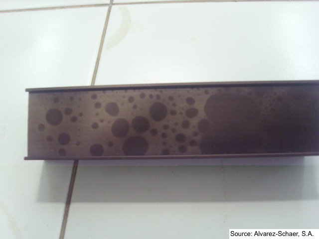
Irregular spots of variable intensity in colouration, situated in lower parts of the profiles.
Retention of air burbles in lower parts of profiles in the racking. Start the coloration equipment before the air is completely evacuated in low parts of profiles.
Racking the profiles with more slope angle between both extremes of profiles. Wait some seconds, before start current in the colouration rectifier to evacuate the air, after introduce each charge in the colouration electrolytic bath.
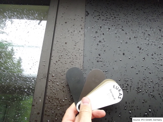
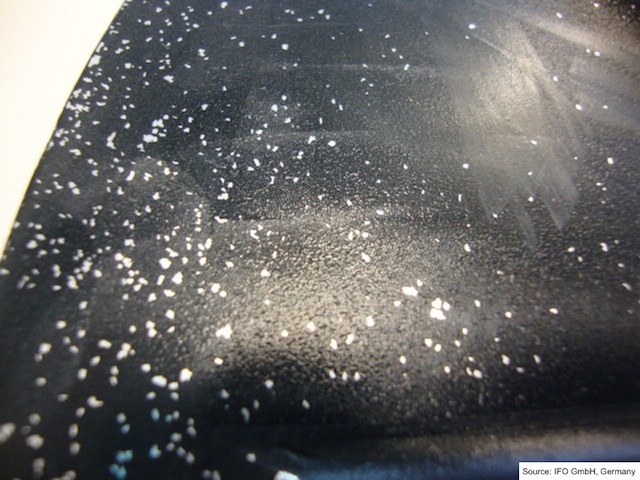
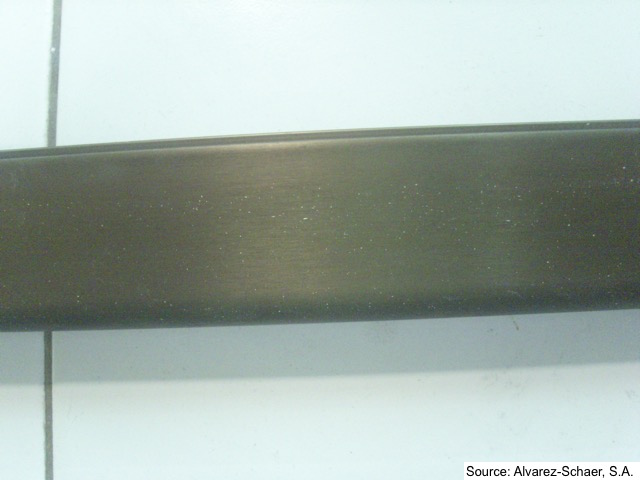
3.28 White Spots in Electrolytic or Dye Colour
- Category: Process defect
- Sub category: Colouration defect
- Defect type: Little white spots in electrolytic or dye colour
- Defect visible after: After electrolytic or dye colouration
- Defect description:
Little white spots in the electrolytic or dye coloured anodised layer.
- Defect cause:
Alkaline gases/vapours
in the surrounding area of colouration.
- Defect remedy:
To improve the
extraction of fumes/gas in alkaline etching position. To prevent
disturbing air currents from etching area to colouration area in the anodising plant.
Little white spots in the electrolytic or dye coloured anodised layer.
Alkaline gases/vapours in the surrounding area of colouration.
To improve the extraction of fumes/gas in alkaline etching position. To prevent disturbing air currents from etching area to colouration area in the anodising plant.
3.29 Non-uniform Anodised Layer
- Category: Process defect
- Sub category: Anodising defect
- Defect type: Non-uniform anodised layer
- Defect visible after: After anodising
- Defect description:
Relief in anodic coating surface. Remains of previous anodising layer.
- Defect cause:
Bad removal of previous anodising layer.
- Defect remedy:
Remove correctly in alkaline etching bath the previous anodising layer in reprocessing. Check and control the alkaline etching bath conidtions.
Relief in anodic coating surface. Remains of previous anodising layer.
Bad removal of previous anodising layer.
Remove correctly in alkaline etching bath the previous anodising layer in reprocessing. Check and control the alkaline etching bath conidtions.